|
|
|
05 to 09 YZ125/250/250F/450F - KX250 - KX450F – 09 CRF450R
Free Piston Modification and Cartridge Bleed Procedure for use with conventional
or SMART Performance 215.VM2.K5 Anti-Vibration fluids
Modifications to the free piston within the YZ/KX/CR air-oil separate (AOS) fork design, also known as the KYB dual chamber, can help alleviate front end push, front wheel rut climb-out and harsh sensations experienced during breaking bumps and downhill sections. Further tuning can be achieved with the use of alternative lighter rate free-piston springs.
The cup design of the KYB free piston is also prone to filling with fluid if the fork is laid flat or inverted, which can further exacerbate poor performance.
To alleviate these concerns, SMART Performance recommends that the KYB free piston be vented by the addition of 2 to 4 holes. These holes allow the air pressure that builds up between the free piston and fork cap to vent to the lower chamber and also allow any fluid within the free piston to drain out and back into the lower chamber. The addition of these holes does not allow the fluid between the lower and upper chamber to exchange. We also recommend that an alternative approach be used for filling and bleeding the upper chamber or cartridge of the fork per the attached procedure.
MODIFYING THE KYB FREE PISTON
Follow the instructions in the Yamaha/Kawasaki/Honda manual to remove the forks from the bike.
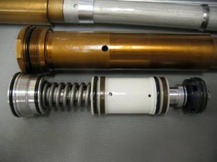
Follow the instructions in the manual to remove the inner chamber of the fork from the lower chamber. The inner chamber is the top damping unit also known as the cartridge assembly.
Mount the upper damper assembly into a vice or holding jig with the cap facing upwards. Only clamp the upper portion of the assembly and always use soft jaws or a towel to avoid damaging the unit. Always protect and never clamp the damping rod (the long 14mm rod at the other end).
Insert a 36mm hex tool into the top of the compression assembly and rotate the unit counter-clockwise until the head of the unit no longer rises. The compression assembly will not rise or easily lift so it may be necessary to listen for the light pop of the last thread. There is no harm from over rotating. Lastly, it may be necessary to hold the upper chamber assembly with a 49mm wrench while turning out the compression assembly. Do not rely on the vice or clamping device to keep the cartridge from spinning.
To release or raise the compression assembly, reach down and slide the damping rod into the cartridge. This will cause the compression assembly to lift or float upwards. If it does not, rotate the compression assembly out another turn or two. Do not push the tip of the damper rod beyond the seal head of the upper chamber.
With the damper rod all the way in, use a small prying tool to work the compression assembly up and out. The compression assembly will be working against a vacuum created by the fluid. You can pry against the wire of the free-piston spring and the edge of the outer cap. Work slowly and protect any sharp edges. Do not allow your tool to make any contact with the free-piston stem.
With the unit out, mount the compression assembly into a holding clamp with the piston (nut end) facing upwards. It’s often best to mount the 36mm tool into the vice then place the compression assembly onto the tool. Avoid clamping directly to the compression assembly.
Use an open end wrench to remove the top piston assembly (stem head) from the rod. Minimal force required. Place head to the side.
Lift off the free piston and free piston spring.
Clean the free piston of any oil residue.
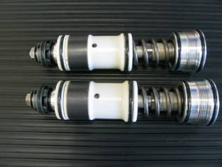
Using a marker (and ruler or caliber if necessary), mark the location of the two bottom holes, 180 degrees apart, so that the holes will be drilled between the lower inner ribs, and just above the top inner edge. On the late model piston, add two additional markings directly above these holes. Make sure to leave enough edge between the hole and the edge of the bushing. See photos.
On the late model piston, drill the 4 holes using a 3mm or .125 inch drill. On the early model piston drill the two holes using a .1875 inch or 4.5 to 4.7mm hole. Remove burrs. Clean drillings using a light duty solvent or warm wash. Blow clean with compressed air.
Reinstall the spring (and spring bushing if used) and the free piston. Inspection and cleaning of the free piston shaft and seal is also recommended. Do not use highly volatile solvents (carb clean) on the free piston seal. NOTE: To further alleviate sensations from braking bumps and downhill sections, we recommend the use of SMART Performance/SPI-Racing free piston spring kits.
Reinstall the valve stem to the rod. Apply
some light duty thread lock (such as Loctite blue) to threaded end of the
rod.
INSTALLING THE VALVE ASSEMBLY AND BLEEDING THE CARTRIDGE
If you have any questions, concerns, problems or doubts with any of this, do not hesitate to contact us via phone or email or reach us in the suspension forum at ThumperTalk.com. Detailed shock rebuilding procedures are also available.
![]()
![]()
![]()
![]()
![]()
![]()
![]()
![]()